For telecom systems integrators, a 48V LiFePO4 rack battery should be accepted against two sets of evidence: factory results for the approved battery configuration, and site results for the installed power and monitoring system. A capacity label or a successful power-on check cannot establish both.
FAT vs SAT: two stages of a telecom battery acceptance test
FAT means factory acceptance test: it checks the agreed battery configuration and test evidence before shipment. SAT means site acceptance test: it checks the installed battery within the site’s power and monitoring system. Both matter because factory results establish the equipment baseline, while site verification addresses the actual load, installation and controller/NOC connections.
Use this proposed checklist to agree responsibilities, measurements and pass criteria with the battery supplier, power-system vendor and network operator before testing starts.
| Evaluation Stage |
FAT |
SAT |
| Configuration |
Verify approved battery configuration |
Verify installed battery identity |
| Electrical |
Review test results and limits |
Verify site voltage and load behavior |
| BMS |
Check approved protection functions |
Verify alarm reporting |
| Communication |
Confirm interface and protocol |
Confirm controller/NOC communication |
| Runtime |
Review agreed capacity test |
Validate site backup requirements |
| Documentation |
FAT report |
SAT report and handover records |
Freeze the acceptance specification before the FAT
Before 48V telecom battery testing begins, identify the exact assembly being purchased: battery part number, drawing revision, BMS hardware and firmware, communication option, accessories and permitted module arrangement. Link each requirement to a document revision and a named approver. Record unresolved items as open actions instead of treating a sample approval as permission to change the production configuration.
Define the electrical and mechanical baseline
Create a shared settings sheet covering the battery operating envelope, rectifier charging controls, current limits, load-disconnect behavior and recovery conditions. Review any existing lead-acid charging functions with the relevant suppliers; use settings approved for the selected battery and controller.
Polarity and earthing also belong in this review. ETSI EN 300 132-2 V2.8.1 addresses the −48 V DC interface at ICT equipment. Referencing that standard does not establish that a particular battery is compatible or certified. The project drawings must define the actual return and earthing arrangement.
For the rack installation, agree dimensions, supported weight, mounting method, service access and cable clearance. Check the complete cabinet arrangement, including support trays or rails specified for the module. Assign responsibility for the cabinet, DC protection and field cabling explicitly.
Define the communication baseline
Specify the physical interface, connector pinout, protocol revision, addressing and any required gateway. Then list the information the operator actually needs: pack voltage, current, temperature, state of charge, alarms and communication status, where supported. A CAN or RS485 interface name alone does not prove that the receiving equipment interprets the data correctly.
The Vertiv NetSure lithium battery application guide illustrates how monitoring features and controller settings depend on the supported battery and software configuration. It is a useful example of why configuration review matters, rather than evidence of MYLION compatibility with that system.
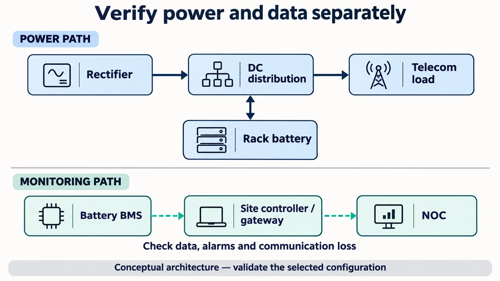 Conceptual architecture: verify power delivery and monitoring separately for the selected system.
Build the telecom battery FAT record
Ask for an agreed FAT procedure before the inspection. It should identify the test sample, instruments, measurement points, operating conditions, acceptance limits and required records. Distinguish tests witnessed on a project sample from routine checks required on shipped units. Define the sampling scope in the purchase specification.
| FAT item |
Evidence to retain |
Acceptance basis |
| Configuration identity |
Part number, serial number, drawing and BMS revisions |
Matches the approved purchase specification |
| Capacity or energy test |
Current or power profile, temperature, endpoint and measured result |
Agreed method and model-specific limit |
| Load behavior |
Voltage and current traces during representative demand changes |
No unexpected interruption within the approved envelope |
| Charging behavior |
Approved settings and recorded charge response |
Battery and rectifier requirements remain satisfied |
| Protection and alarms |
Approved functional checks, event records and recovery observations |
Matches the agreed cause-and-effect matrix |
| Mechanical inspection |
Dimensions, mounting arrangement, accessories and inspection record |
Matches the approved installation drawing |
Record the capacity test’s starting charge condition, discharge rate, temperature, termination rule and whether the result is measured in Ah or Wh. For a constant-power telecom load, an energy record helps relate the factory result to the intended duty.
Protection checks should follow a supplier-approved procedure using appropriate test equipment or simulation. Keep destructive qualification testing separate from routine project acceptance. Do not create faults on an operating network merely to demonstrate a BMS function.
Trace each alarm from event to recovery
Build a cause-and-effect matrix with one row for each required event. Include the stimulus, local indication, reported data or alarm, severity, receiving point, clearing condition and expected recovery. Confirm which events the selected BMS actually exposes and which require the site controller or a separate sensor.
Treat communication loss as a separate test case. Agree how stale or unavailable battery data should appear and what action the controller should take. A normal-looking last reading must not be mistaken for a current measurement. Record both the alarm appearance and its clearance after the approved recovery sequence.
Verify telecom battery integration at the site
During LiFePO4 battery commissioning, the SAT checks site variables that a factory bench cannot fully represent: field cables, distribution losses, controller configuration, cabinet conditions and the network operations center (NOC). Start by checking delivery condition and reconciling installed serial numbers and software versions with the FAT record.
- Installation: record the approved mounting, support, clearances, connection inspections and applicable installation checks performed by qualified personnel.
- Settings: export or capture the actual rectifier and battery configuration, then compare it with the approved settings sheet.
- Outage behavior: under an operator-approved test plan, record the load response, DC voltage, battery current and any service interruption during a controlled loss of normal supply.
- Recharge: observe restoration of supply, the division of available power between the live load and battery charging, and recovery to the agreed ready state.
- Remote monitoring: verify the required battery data, alarm identity, site identity, severity, timestamps and clearance at the NOC receiving system.
A local controller screenshot verifies only part of the monitoring path. Where remote alarms are in scope, retain evidence from the receiving system as well. Name the team responsible for gateway configuration and alarm mapping so that a missing NOC event has a clear owner.
Agree runtime and recharge criteria separately
A statement such as “four hours of backup” is incomplete without a load profile and endpoint. Define the equipment included, initial charge condition, ambient conditions, allowed discharge endpoint and required service continuity. State whether acceptance uses a load bank, the actual network load or a combination, and record the differences.
Recharge readiness needs its own criterion. Restored AC power does not mean that the battery is ready for another outage. The test should assess the agreed recovery target while the site continues to serve its load. Define the observation period and completion condition rather than inferring readiness from bus voltage alone.
For approved multi-module systems, include module availability and current-sharing observations in the SAT scope. Use the supplier’s approved topology and configuration. Agree the intended response to a module becoming unavailable; do not infer redundancy or allowable parallel quantity from the number of rack positions.
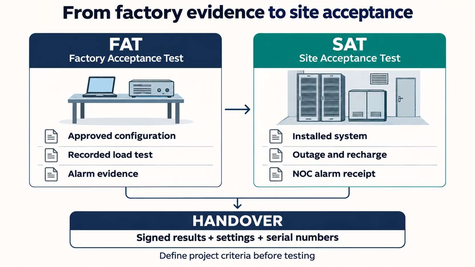 Proposed project workflow: factory evidence, installed-system acceptance and a documented handover.
Close the handover package before a wider rollout
The handover should let another engineer identify what was accepted and reproduce the relevant settings. Include the signed FAT and SAT results, installed serial-number list, approved drawings, settings exports, firmware and protocol revisions, alarm matrix, operating instructions and a list of remaining actions with owners.
Classify findings as accepted, requiring correction, or accepted with a documented concession. Record who has authority to approve each category. A successful factory test should not automatically close an unresolved site issue, and a site adjustment should be reflected in the final configuration record.
For repeat deployments, define which changes trigger review or retesting. Examples include a different BMS revision, rectifier model, communication gateway, module count or cabinet arrangement. This makes an approved pilot a controlled reference for rollout rather than a blanket approval for every future site.
Practical acceptance summary for telecom integrators
Before accepting a 48V LiFePO4 rack battery, confirm that factory evidence and site verification have each met the agreed criteria.
Factory evidence
- Match the battery identity, drawings, BMS revision and ordered options to the approved specification.
- Retain the agreed capacity/load results with test conditions, plus the approved protection and communication checks.
Site verification
- Match installed serial numbers and settings to the accepted configuration; verify site voltage, load behavior and installation records.
- Confirm runtime and recharge against separate project criteria, and verify required alarms and communication loss at the controller and NOC where in scope.
- Close deviations and obtain signed SAT and handover records with clear ownership of any remaining actions.
Evaluate MYLION rack batteries for your telecom project
Start with the MYLION 48V LiFePO4 rack battery range and request the model-specific datasheet, installation drawing and available BMS communication details. Evaluate the shortlisted configuration against the same factory and site acceptance criteria used for the project.
This model can be evaluated for telecom equipment rooms, ISP network cabinets and OLT backup projects. Compare its confirmed operating limits, mounting requirements and BMS configuration with your rectifier, load profile and cabinet. Review the agreed capacity-test conditions before defining the site’s backup target.
This is another nominal-capacity option for project evaluation. Assess the selected revision’s electrical and mechanical requirements, charging conditions and approved module arrangement against the intended load and backup requirements. Confirm the complete system’s suitability before deciding between the 100Ah and 150Ah options.
Communication interfaces, supported protocols, parallel arrangements and compatibility with your rectifier, controller or NOC are subject to configuration confirmation for the selected model. Agree on-site SAT responsibilities separately with the integrator, operator and any appointed service provider.
For application and upgrade context, see our guide to 48V LiFePO4 rack batteries for telecom backup.
To begin a technical discussion, provide your rectifier and controller models, system drawings, load profile, target backup and recharge requirements, rack constraints, monitoring requirements, destination market and expected deployment quantity. Include your proposed FAT and SAT checklist so that documentation, interfaces and acceptance responsibilities can be reviewed alongside the battery choice.
Request a MYLION model-specific technical evaluation and quotation. Ask the team to confirm the proposed configuration and available product documentation before sample approval, then agree the test scope and pass criteria before planning a wider rollout.
Frequently asked questions
What is the difference between FAT and SAT for telecom batteries?
FAT verifies the agreed battery configuration and evidence before shipment. SAT verifies the installed system at the telecom site, including load behavior, settings and the required monitoring path.
What should be included in a 48V LiFePO4 battery FAT checklist?
Include configuration identity, capacity or energy test conditions, representative load and charging behavior, approved protection checks, communication checks and mechanical inspection. Define the acceptance limits and records before testing.
How is a telecom battery SAT performed?
Battery SAT testing follows an operator-approved procedure: inspect the installation, reconcile settings and serial numbers, observe controlled outage and recharge behavior, and verify required controller/NOC data and alarms against project criteria.
Why should battery runtime and recharge be tested separately?
Runtime measures service continuity during an outage. Recharge assesses recovery to the agreed ready state while the site still serves its load. Passing one test does not establish the result of the other.
What documents are required for telecom battery handover?
Agree the required set in the project contract. It typically includes signed FAT/SAT reports, serial numbers, approved drawings, settings exports, BMS firmware and protocol revisions, an alarm matrix, operating instructions and unresolved-action records.
 English
 Deutsch
 Español
 Français
 Italiano